Product Description
DEMONSTRATION BOARD OF AUTOMOTIVE BODY CAN SYSTEM
Description:
Standard Configuration:
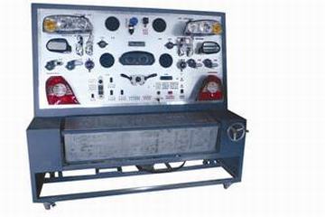
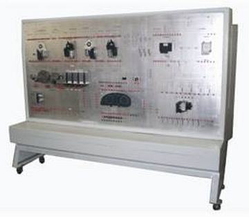
Adopt original plant accessories, including central control computer, left-front, right-front door control computer, left-back door control computer, right-back door control computer, switches of door locks, courtesy lamp, switches of illumination, engine computer, gearbox computer, ABS computer, instruments and ignition key.
Through gateway connection of instruments combination, power system data network and comfort system data network can be connected, which forms integrated entire vehicle CAN network systems. Combining physical vehicle, it completely display structure and work process of data transmission network power system of VolksWagen.
This equipment can test CAN data transmission network of the whole comfort system and terminal control unit through computer diagnostic apparatus of auto breakdown.
Set up faults by hand or remote, at most 96 fault points.
There are two models: teaching and training. It's convenient for teachers to teach and train.
Diagnose connections are configured to connect testing equipment special for motor vehicles.
Teaching Function:
It's fit for theories and practice teaching of CAN-bus system for all kinds of school and training institution.
It can completely show the structure and working principle of CAN-bus system to help students understandabstract theory.
It can stimulate, diagnose and test the common faults of CAN-bus system to train students' ability of analyzing and solving problems.
It is configured with computer diagnose terminators to test voltage signal.
Draw engine structure diagram to analyze circuit.
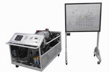
Extend Configuration
Test-bed and PC carry on real-time communication. The computer monitor can display work status of all sensors and actuators of electronic control system. You can set up electric circuit abruption and rosin joint of electronic control system through computers.
Configuration of multi-media network teaching and learning environment that uses a multi-board manner, each student configures information display device, the main components terminal voltage detection device and information input device, so that students learn to analyze and solve practical problems under teachers' leadership;
Standardized evaluation system, print out students' achievement lists. |
Advanced Automotive CAN Network TrainingDesigned for educational settings and professional development, this demonstration board enables hands-on experience with CAN bus systems. With integrated LED status indicators, real-time communication can be observed and analyzed. The inclusion of user manuals and wiring diagrams facilitates straightforward setup and usage, making it ideal for both students and industry trainers.
Flexible Fault Simulation and ExpansionEquipped with manual switches for fault insertion, this board allows users to simulate common network errors and observe system responses. The expansion port supports connectivity for additional modules, giving trainers and researchers greater versatility in lesson development and experimental scenarios.
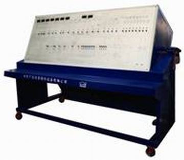
Durable and Safe ConstructionConstructed from aluminum and high-quality acrylic, the board offers excellent durability and visibility of circuitry. It features comprehensive safety provisions like overcurrent and reverse polarity protection, and operates from a standard 220V/50Hz supply via included adapters. The system is designed for both portability and secure classroom or lab installation.
FAQs of DEMONSTRATION BOARD OF AUTOMOTIVE BODY CAN SYSTEM:
Q: How do I use the demonstration board to simulate a fault in the CAN bus network?
A: Fault simulation is achieved using the boards manual switches, which allow you to introduce specific errors or interruptions on the CAN bus. This enables trainees to observe and troubleshoot communication failures in real time.
Q: What applications is the Demonstration Board of Automotive Body CAN System suitable for?
A: This board is designed for automotive CAN bus training and educational demonstration. It is ideal for universities, technical training centers, and automotive workshops to help users understand CAN communication protocols and network diagnostics.
Q: When should I use the expansion port on the demonstration board?
A: The expansion port can be used whenever additional modules, sensors, or learning circuits need to be integrated. This is particularly useful for advanced experiments or expanding lessons beyond the four standard CAN nodes.
Q: Where can this demonstration board be installed or mounted?
A: It is designed for both table top and wall mount installations. The rectangular aluminum frame makes it suitable for use in classrooms, laboratories, or automotive training facilities.
Q: What are the key safety features of this automotive CAN demonstration board?
A: The system is equipped with overcurrent and reverse polarity protection to ensure safety during operations. Comprehensive documentation also guides safe set-up and handling.
Q: How do the LED status indicators and digital display enhance training?
A: LED indicators on each node provide immediate visual feedback on node status and communication activity, while the digital screen enables real-time monitoring of specific functions, strengthening practical understanding for learners.
Q: What are the main benefits of using this demonstration board for CAN training?
A: The hands-on approach, real-time network simulation, quick connection terminals, and fault insertion capability provide an immersive learning experience. Comprehensive documentation supports easy setup and operation, ensuring effective knowledge transfer for trainees.


 English
 Spanish
 French
 German
 Italian
 Chinese (Simplified)
 Japanese
 Korean
 Arabic
 Portuguese