Product Description
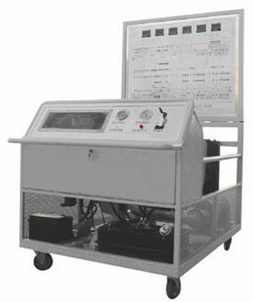
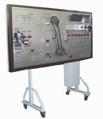
ELECTRIC CONTROL SYSTEM OF ENGINE TEST BED Description:
Teaching Function:
It can completely show the structure and working principle of engine electronic system to help students understand abstract theory.
It can imitate, diagnose and test the common faults and troubles of engine electronic system. Train students to analyze and solve practical problems.
Extend items: Multimedia network teaching, the establishment of specialized teaching and learning environment, and standardized evaluation system.
Standard Configuration:
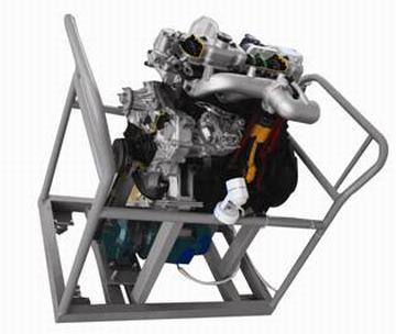
Components are from original Santana 2000GSL, including sensors, actuators and control computers.
Set up breakdown by hand or remote, at most 96 points.
Plot engine structure diagram to show working process.
Extend Configuration
Test-bed and PC carry on real-time communication. The computer monitor can display work status of all sensors and actuators of electronic control system. You can set up electric circuit abruption and rosin joint of electronic control system through computers.
Configuration of multi-media network teaching and learning environment that uses a multi-board manner, each student configures information display device, the main components terminal voltage detection device and information input device, so that students learn to analyze and solve practical problems under teachers' leadership;
Standardized evaluation system, print out students' achievement lists.
|
|
Purpose-Built for VW Santana 2000 EnginesThis engine test bed is specifically tailored for the VW Santana 2000, ensuring precise compatibility with original engine management sensors and control systems. Its user-friendly interface and real-time data acquisition make it an essential tool for accurate diagnostics, monitoring, and testing, supporting both manual and electronic control.
Safety and Quality AssuranceEquipped with advanced protection features, including fuse control, emergency stop mechanisms, and short-circuit guards, the system prioritizes operator and equipment safety. It adheres to rigorous standards: ISO9001 for manufacturing, as well as electrical safety and EMC requirements, making it dependable for regular use in demanding environments.
Effortless Operation and VersatilityThe control system boasts color-coded terminal boards, plug-and-play connections, and test point sockets for convenient wiring and troubleshooting. Whether in hospitals, training institutes, or automotive workshops, users can take advantage of its digital displays, overload protection, and mobility with lockable casters to streamline engine testing and research.
FAQ's of ELECTRIC CONTROL SYSTEM OF ENGINE TEST BED (FOR VW SANTANA 2000):
Q: How do I connect the engine control system to a VW Santana 2000 engine?
A: Connecting is straightforward due to the color-coded terminal board and plug-and-play connections. Each sensor and actuator port is clearly labeled, allowing for hassle-free wiring. Simply attach the corresponding engine harness to the matching ports and secure all connections before powering on.
Q: What are the main benefits of using this test bed for engine diagnostics?
A: This engine test bed offers precise diagnostics through real-time digital displays of RPM, voltage, faults, and sensor status. It ensures safety with overload and short-circuit protection and enables easy fault diagnosis, making it ideal for both professional and training environments.
Q: When should the emergency cut-off be used during testing?
A: The emergency cut-off is designed for immediate termination of all system functions in case of unexpected faults or hazards, such as electrical shorts or engine malfunction. Use it promptly whenever abnormal operation is detected to prevent damage or accidents.
Q: Where is this control system best utilized?
A: This control system is versatile and suitable for engine research labs, vehicle diagnostics centers, hospitals (for educational or maintenance purposes), and automotive training institutes, particularly where VW Santana 2000 engines are serviced or studied.
Q: What is the process for performing a diagnostic test on this system?
A: Begin by securely connecting all sensors and actuators, then switch on the main power. Start the engine using the control panel, monitor digital readouts, and observe sensor signals and faults. Use the ECU signal testing and diagnostic output terminals for in-depth analysis. Faults and sensor statuses will be displayed in real-time for efficient troubleshooting.
Q: How does the equipment ensure safety during operation?
A: Safety is maintained through a multi-tier approach: fuse protection guards against overload, an emergency cut-off halts operation instantly, and short-circuit shields protect components. All electrical wiring is compliant with EMC standards for added operational security.
Q: What maintenance is required to keep the control system in optimal working condition?
A: Regularly inspect connections, check fuses, and ensure the system is dust-free. Test the emergency stop and indicator lamps periodically. Maintain proper environmental conditions (temperature between -10C to 60C) and store the unit in a dry, clean area when not in use.


 English
 Spanish
 French
 German
 Italian
 Chinese (Simplified)
 Japanese
 Korean
 Arabic
 Portuguese